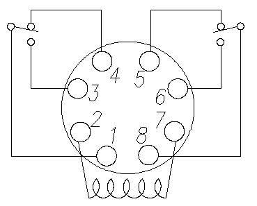
At first glance, the 11 Pin Relay Diagram might seem like a complex and confusing piece of equipment. However, it is actually one of the most important pieces of wiring in any electrical system and understanding it is essential for anyone working with electrical components. In this article, we’ll explore what an 11 Pin Relay Diagram is, how it works, and how to use it effectively.
An 11 Pin Relay Diagram is a wiring diagram used for connecting electrical components together in a series. It consists of a set of pins that are connected to each other through a series of wires. The pins are labeled and the wires are colored based on their function. This makes it easy to identify the connections between different components and to troubleshoot any problems that may arise. The basic premise of the 11 Pin Relay Diagram is that it connects multiple components in a series so they can all be powered up at the same time.
The 11 Pin Relay Diagram is typically used in high voltage systems, such as those found in factories, buildings, and other large-scale projects. It is also used in chemical plants and other industrial applications. The diagram is designed to make it easy for technicians to connect components safely and quickly. By following the diagram, technicians can ensure that no wire crosses its intended path and that all connections are secure.
Using an 11 Pin Relay Diagram is relatively simple. Once all of the connections are made and the wires are connected, the diagram will show the entire electrical system and its connections. It is important to note that if any of the connections are incorrect, it can cause serious damage to the electrical system and even cause injury or death. Therefore, it is always advisable to consult an expert electrician before attempting to work with an 11 Pin Relay Diagram.
Understanding and using an 11 Pin Relay Diagram is essential for anyone working with electrical components. It is a simple and effective way to ensure that all components are connected properly and that no wires cross their intended paths. By taking the time to understand the diagram and its connections, you can ensure the safety of yourself and those around you.
Item 88ahpx 74 240vac 88hp Series Hermetically Sealed Plug In Special Purpose Relays On Struthers Dunn

Fwsc Relay Cover For Use With 11 Pin Octal Rs Components
S3 Mp Releco Relay Socket For Use With Mrc Series 11 Pin 250v Ac 437 799 Rs Components
Electrical Electronics Engineering 8 Pin Pla Relay Connection You Can Join Our Family Learneee Android App For More Technical Stuff Visit Bio 1 Share With Your

Mze Electroarts Entertainment Mzentertainment Com Dr Zee Work On Line Relays Sensors Solenoids
Pinoy Elektrisyan 14 Pin Relay Pinout Facebook

Relay Socket Pf113a 11 Pin Octal Base For Mk3p I Jqx 10f 3z Jtx 3c H3cr

China 11 Pin Relay Socket Manufacturers And Suppliers Factory Whole Meishuo Electric
Omron Twin Timer Relay Battery Driven Fuel Pump All About Circuits

Automotive Relay Diagram 4 5 Pin Wiring

How To Wire A Relay

8 Pin Round Base Socket Pf083a Pack Of 5 Pcs Automation Controls

11 Pin Relay Base Pf113a E Meishuoen

Dpdt 220vac 5a 8 Pin Terminals Relay Technical Data

C3 R20 Dc 24 V Releco Plug In Latching Power Relay 24v Coil 10a Switching Cur Dpdt Rs Components
286 287 Series Squre Base Time Delay Relays On Struthers Dunn

8501kpdr13v51 Plug In Relay 11 Pin 3pdt 10 Amp At 277 Vac 12 Vdc Coil Schneider Electric Usa

China Electrical Hh53p My3 Omron 11 Pin Spdt Power 24v Dc Relay


