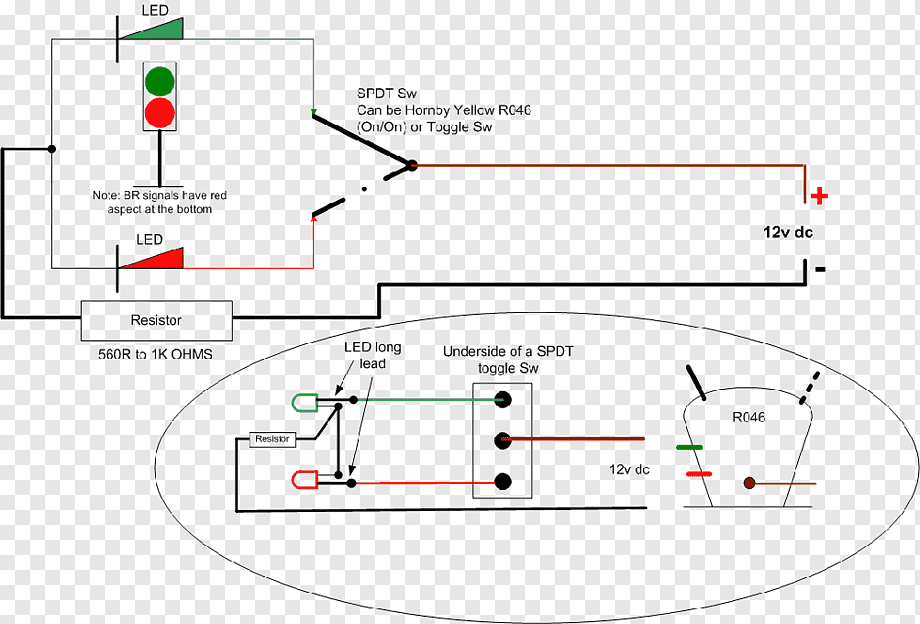
Latching relays are a type of electrical relay that is designed to remain switched on or off for long periods of time, without any external power source. They are typically used in situations where there is a need for the relay to be switched on or off for extended periods. The latching relay circuit diagram is a diagram that shows the components and wiring of a latching relay circuit.
A latching relay circuit consists of a power supply, a set of contacts, a coil, and control switches. The power supply provides the current to the coil. When the control switch is switched on, the current flow energizes the coil, which causes the contacts to close. When the control switch is switched off, the current flow stops, and the contacts open again. The functioning of the latching relay circuit is based on the hysteresis effect, which means that the contacts will stay in either the “on” or “off” position until the switch is changed.
The latching relay circuit diagram is useful for troubleshooting problems in latching relay circuits. By studying the diagram, technicians can identify where the problems might be located in the circuit. They can also determine what components need to be replaced or adjusted to fix the problem. By doing this, technicians can save time and money by avoiding unnecessary repairs.
In addition, the latching relay circuit diagram is a great educational tool for students and engineers who are just starting out in learning about latching relays. It helps them understand how the different components are connected and how they interact with each other. This knowledge can be used to design and build latching relay circuits for a variety of applications.
In conclusion, the latching relay circuit diagram is a tool that is used to help technicians diagnose and repair latching relay circuits. It can also be used as an educational tool for students and engineers. By understanding how the components of a latching relay circuit are connected and how they interact, one can design and build their own latching relay circuits.

Wiring Diagram Electrical Switches Latching Relay Multiway Switching Trim Tabs Angle Text Wires Cable Png Pngwing

Single Pushon Latching Relay Engine Start Circuit
Wiring Octal 11 Pin Latching Relay Cr4 Discussion Thread

Request Latching Relay Switching Circuit Sabrotone

Ic Drives Up To Four Single Coil Latching Relays

Drive A Single Coil Latching Relay Without An H Bridge Circuit Edn

0 728 02 Durite 12v 25a Latching Relay Changeover

Latching Relay What Is It Circuit Diagram And How Works Electrical4u

Latching Relay Working Principle Advantages Applications

Light Switch Wiring Latching Relay Transpa Png 375x370 Free On Nicepng

Electrical Switches Wiring Diagram Latching Relay Schematic Png Clipart Angle Area Black And White Circle

Relay Latching Circuit Using Push On Instrumentation Tools

Latching Relay To Use A Momentary On

Relays Mechanical Latching Monitoring

Mechanical Latching Relay Working Your Electrical Guide

Simple Latch Circuit Diagram With Transistors

Electrical Diagram Of An H Bridge With Four Relays Designed To Control Scientific
