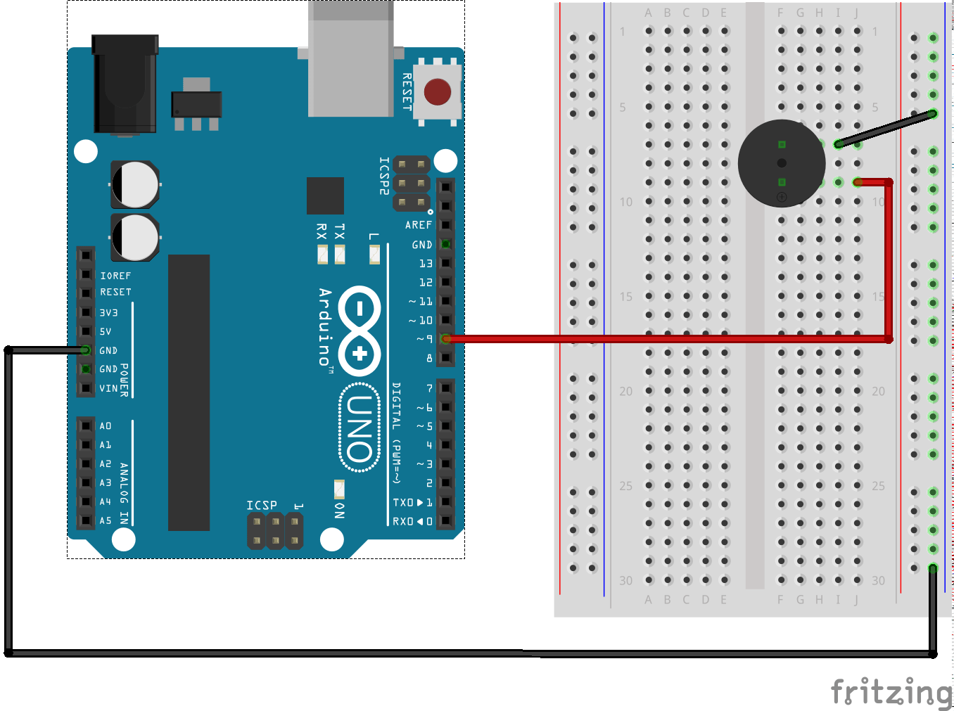
The Piezo Buzzer is an essential component of any electronic circuit, providing a reliable and easily audible alert for any number of applications. But while the buzzer itself is straightforward enough to understand, understanding the circuit diagram can be more complex. In this article, we’ll take a closer look at the Piezo Buzzer Circuit Diagram, explaining each part of the diagram and how it works.
At the center of the Piezo Buzzer Circuit Diagram is the Piezo Element. This is the device that produces the audible sound when activated. The Piezo Element is connected to the rest of the circuit via two wires: one positive (or +) and one negative (or -). The positive wire connects to a battery or power source, while the negative wire connects to a resistor, capacitor, or other electrical devices. Depending on the application, the resistor and capacitor may be used to control the sound frequency and volume.
In addition to the Piezo Element, the Piezo Buzzer Circuit Diagram also includes a switch. The switch allows the user to turn the buzzer on or off, depending on the needs of the application. A typical switch is a toggle switch, which can be turned on and off with the flick of a finger. By controlling the switch, the user can choose when the Piezo Buzzer should sound and when it should not.
Finally, the Piezo Buzzer Circuit Diagram also includes ground connections. This is a safety measure to ensure that the sound produced by the buzzer does not cause any electrical damage. Ground connections are usually connected to the negative side of the circuit, but it can also be connected to both the positive and negative sides.
As you can see, the Piezo Buzzer Circuit Diagram is relatively simple and straightforward. While understanding the individual components of the diagram can be a bit intimidating, once you have a basic understanding of the different parts of the diagram, you should be able to safely and effectively use your Piezo Buzzer.

Driving Piezo Buzzer With N Mosfet General Electronics Arduino Forum

Electronic Projects

Buzzer Driver Elr Magazine

Solved Peizo Electric Buzzer Drive Circuit Forum For Electronics

Piezoelectric Buzzer For Driver Circuit Built In Lf Pb24p34b Ariose Electronics Co Ltd

How To Interface Piezo Buzzer With Arduino Electrovigyan

Classification Of Smd Buzzer And Driven Circuit Keliking Micro Piezo Ceramic Transducer Sensor Manufacturer

Arduino Beep Speaker Deals 52 Off Www Ingeniovirtual Com

Db Unlimited Technical Articles Piezo Digital Drive

Electronic Projects

Making Simple Buzzer Circuit Eleccircuit Com

Arduino Piezo Buzzer Tutorial

Magnetic And Piezo Buzzer Circuits

Simplest Piezo Driver Circuit Explained Homemade Projects

Pwm With A Piezo Buzzer Nordic Q Devzone

Electronic Projects

Simple Piezo Buzzer Circuit With Um66t Ic Circuits Diy

3 Terminal 85db Self Drive Piezo Buzzer For Smoke Detector From China Manufacturer Kailitech

Piezo And Magnetic Buzzers
