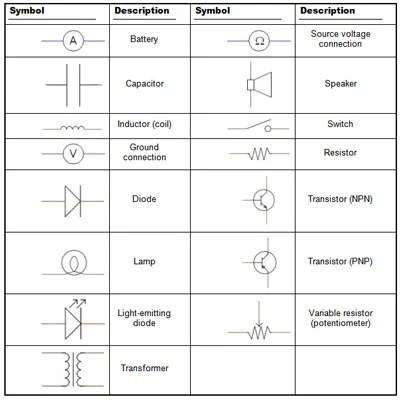
Circuit symbols are essential components of any electrical system. They help to identify different components and how they interact with each other, allowing engineers to design systems that are safe, reliable and efficient. Understanding the different symbols used in circuit diagrams is an important part of any electrical engineering project.
One of the most common symbols is a resistor. This component is used to reduce current or voltage in an electronic circuit, and it’s represented by a zigzag line. A capacitor is another key component, and it looks like two parallel lines with a curved line between them. Capacitors are used to store energy and can be seen in radios, televisions and many other electronic devices.
Switches are also very important components, and they’re represented by a triangle with a line through it. Switches are used to control the flow of electricity in a circuit, and they can be used to turn power on or off. The triangle symbolizes the input side of the switch, while the line through the triangle symbolizes the output.
For more complex circuits, multiple components may be connected together. These connections are represented by arrows, which show the direction of the current. If an arrow points away from a component, it means that the current is flowing away from the component. If an arrow points toward a component, it means that the current is flowing into the component.
Circuit symbols are essential components of any electrical engineering project. By understanding how these symbols work, engineers can design safe and reliable systems that use these components to their full potential. With a solid understanding of circuit symbols, engineers can create amazing electrical systems that are optimized for maximum efficiency.

Electrical Symbols Gray Furnaceman Furnace Troubleshoot And Repair

How To Read A Schematic Learn Sparkfun Com

Electronic Component Lists And Schematic Symbols Free Online Pcb Cad Library

Electrical Symbols On Wiring Diagrams Meanings How To Read And What They Mean

Electronics Schematics Commonly Symbols And Labels Dummies

Pneumatic Circuit Symbols Explained Library Automationdirect

Schematic Symbols The Essential You Should Know

What Is The Meaning Of Schematic Diagram Sierra Circuits

Electronic Components Symbols Reading And Understanding Various

Electrical Symbols Switches And Relays

Electrical Symbols Electron S

Electrical Symbols Resistors

Electrical Symbols Semiconductor

How To Read A Schematic Learn Sparkfun Com

Common Automotive Diagram Symbols

Electronic Circuit Symbols Component Schematic Electronics Notes

Hydraulic Symbology 301 Electrical And Electronic Symbols
