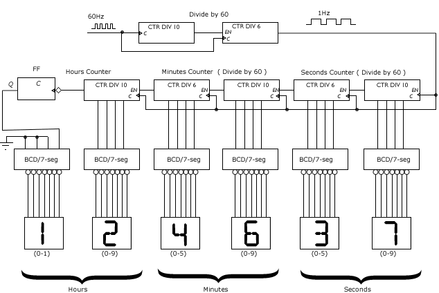
Creating a digital clock circuit diagram in Matlab Simulink is a great way to enhance your understanding of electronics and computer programming. This tutorial will walk you through the basics of setting up your circuit diagram and provide an example of how to use the tools available in Matlab Simulink to create a digital clock.
To begin, open the Simulink library and select the “Digital Clock” template. You will then be presented with a blank canvas where you can begin designing your circuit. First, add the components you need to create the circuit. These include a power source, a clock oscillator, and a logic gate. Connect the components with the appropriate wires, ensuring that they are properly connected.
Next, you will need to set up the logic gate. This is done by using the logic simulator in the Matlab Simulink library. Here, you can configure the logic gates for the desired operation of the circuit. For example, when the clock oscillator is giving out a signal, the logic gate should output a pulse. Finally, connect the power source to the components and set the clock oscillator to the desired frequency.
Once the circuit is complete, you can now simulate the design using the Simulink library. This allows you to see how the circuit behaves and make adjustments if needed. You can also use this feature to test the performance of your design. When you are satisfied with the results, you can save the circuit diagram so you can refer back to it later.
In conclusion, creating a digital clock circuit diagram in Matlab Simulink is not only a great way to gain a better understanding of electronics but it is also a great way to practice computer programming. With just a few clicks, you can put together a functional circuit and test it in the simulator. Once you are comfortable with the design, you can save it for future reference.
Wind Turbine Blockset In Matlab Simulink General Overview And Description Of The Models

Estimate State For Digital Clock Matlab Simulink
The Matlab System Control Toolbox

Digital Clock Circuit Using Ic 555 And 4026 Diy Electronics Projects

Control Tutorials For Matlab And Simulink Extras Basics Tutorial Block Libraries
How To Make A Simple Circuit Diagram Of Digital Clock Quora
Rounded Text Qxd Page 1
Simple Digital Clock File Exchange Matlab Central

Simulate The Circuit Using Digital Simulation Techniques Electrical Engineering

Digital Clock Circuit Using Ic 555 And 4026 Diy Electronics Projects

Control Tutorials For Matlab And Simulink Basics Tutorial Interaction With
Circuit Diagram How Digital Clocks Work Howstuffworks

Control Tutorials For Matlab And Simulink Introduction Digital Controller Design

Digital Alarm Clock With 8051 89c51 Microcontroller

Mathworks Introduces Release 2021b Of Matlab And Simulink Microwave Journal Signal Integrity

Simulation Framework Of Wireless Sensor Network Wsn Using Matlab Simulink Software Intechopen

Leveraging The Simulink Control Design Toolbox For Quanser Coupled Tanks System

The Matlab Simulink Model Scientific Diagram

Control Tutorials For Matlab And Simulink Basics Tutorial

Interface Ds1307 Rtc Module With Arduino Display Date Time On Oled
