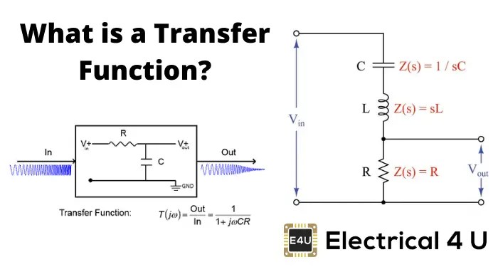
Circuit diagrams have become an essential part of electrical engineering and electronics. They are used to represent the various components of a circuit, such as switches, resistors, capacitors, and transistors, as well as their connections. Circuit diagrams are often used in the design process, allowing engineers to quickly identify connections, troubleshoot problems, and create solutions.
The main function of a circuit diagram is to provide a visual representation of how a circuit works. This allows engineers to quickly analyze the behavior of a circuit and find any potential issues or discrepancies. By providing a graphical representation of the components and their connections, circuit diagrams can make it easier for engineers to understand how a circuit works. Additionally, circuit diagrams can be used to generate accurate simulations of a circuit, allowing engineers to verify its behavior before constructing a physical prototype.
Circuit diagrams are also commonly used to troubleshoot and diagnose problems with existing circuits. By looking at the diagram, engineers can easily identify any faulty components or connections that need to be replaced or adjusted. This allows them to quickly pinpoint the source of the problem and develop a solution. Furthermore, circuit diagrams can also be used to create new circuits from scratch. By drawing out the diagram and connecting the components according to the diagram, it is possible for engineers to construct working circuits.
In conclusion, circuit diagrams are an invaluable tool for electrical engineers and electronics hobbyists. They allow engineers to quickly understand the behavior of a circuit, troubleshoot existing problems, and create new circuits from scratch. Circuit diagrams also enable engineers to accurately simulate a circuit before constructing a physical prototype, ensuring that the circuit will function as expected. As a result, circuit diagrams are essential for electrical engineering and electronics.

Bluetooth Function Generator Circuit Homemade Projects

Multi Function Radar Jma 3910 3925 Schematic Diagram Dimension Jrc An Radio Co Ltd

A Basic Equivalent Circuit Diagram For Switched Mode Dc Converter Scientific

Electronic Projects
61245127 R C Full Function Vehicle Schematics Circuit Diagram Grandex Development

Icl8038 Mini Function Generator Circuits Eleccircuit Com

Transfer Function Of Control System Electrical4u

A Circuit Diagram Of Oscillator 1 B Absolute Function Scientific

Equivalent Small Signal Circuit Diagram Of Logic Function With Inverter Scientific

Square Wave Generator Using Op Amp Electronic Circuits

Function Generator Circuit Diagram Using Lm324 Ic Its Specification
Solved 1 Write An Expression For The Boolean Function That Chegg Com

Functional Circuit Diagram Of The Sase Electronic Board 1 Scientific

Derive The Transfer Function Of Electrical Circuit Draw A Schematic Diagram An Analogous Mechanical System Homework Study Com

Circuit Diagram Of The Saturated Non Lineal Function Snlf From Scientific

Circuit Diagram Tutorial Explain With Examples And Templates

Solved 6 Given The Following Circuit Diagram Determine Chegg Com

Electrical Symbols Circuits

How To Read A Schematic Learn Sparkfun Com

