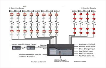
Fire alarm systems are essential for the safety of any property. They detect smoke or heat and alert occupants to evacuate the area quickly. Wiring diagrams for conventional fire alarm systems provide a comprehensive overview of the components and interconnections of the system. By understanding the wiring diagram, technicians can diagnose problems or make changes to the system more easily.
A wiring diagram for a conventional fire alarm system usually starts with the main control panel, which is connected to the power supply, detectors, and alarms. From there, the diagram shows how the power is routed to each of the components. This includes the connection between the detector and the main control panel, as well as the connections between the alarms and the main control panel. The wiring diagram also shows how the system is connected to the fire department or other emergency services.
The wiring diagram also provides information about the types of detectors used in the system. These detectors detect smoke, heat, carbon monoxide, and other hazardous materials. The wiring diagram will show the interconnections between the detectors and the main control panel. It also shows the connections between the detectors and the alarms. In some cases, the wiring diagram will include information on the type of alarm used, such as a horn, strobe light, siren, or other audible alarm.
Finally, the wiring diagram for a conventional fire alarm system will show the connections between the fire department or other emergency services and the system. This includes the connections between the fire department’s control panel and the main control panel, as well as the connections between the fire department’s control panel and the detectors and alarms. By understanding the wiring diagram, technicians can quickly identify any problems in the system and take appropriate action.
Wiring diagrams for conventional fire alarm systems provide a comprehensive overview of the components and interconnections of the system. Understanding the diagram can help technicians diagnose problems or make changes to the system more easily. It is important to remember that the diagram should be read carefully to ensure that all connections are properly made and that the system operates safely.

New Fire Extinguisher Control System Wiring Diagram Solution Ansorl Ltd
Fire Control Life Protection Wiring Diagram Of Conventional Addressable Alarm System Safety Facebook By Adarsh 971 551840039

How Does Conventional Class A Fire Alarm Wiring Work

Hush On
![]()
Which Of The 2 Fire Alarm System Wiring Should You Use Academy
8 Zone Conventional Fire Alarm Control Panel Installation Manual

Activity 1 Electrical Jeffrey A Dianing

A Guide To The Types Of Fire Alarm Systems

System Sensor 1224 Conventional Beam Detector Tvpn

Keep In Touch Ltd

Fire Alarm Control Panel Ck1016 Conventional Linkage Of Systems From China Suppliers 158707112

Fire Alarm System
What Is Intelligent Fire Alarm System Wiring Diagram Etechnog

Conventional Vs Addressable Fire Alarm Systems

Monthly Featured Product West Penn Wire

The Guide To Commercial Fire Alarm Systems Britannia
![]()
Which Of The 2 Fire Alarm System Wiring Should You Use Academy

Hard Wired Vs Wireless Fire Alarm Systems News
What Is Intelligent Fire Alarm System Wiring Diagram Etechnog


