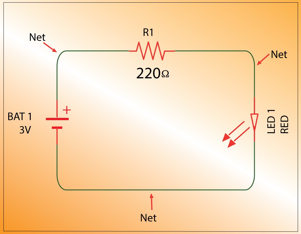
Circuit diagrams are the language of electrical engineering and, as such, they are an essential tool for anyone working in the field. They are used to create and communicate the design of an electrical system or circuit, allowing engineers to visualize their ideas before they build them. But what is the main purpose of a circuit diagram?
The primary purpose of a circuit diagram is to provide a visual representation of an electrical circuit or system. Circuit diagrams use symbols and icons to represent different components within the circuit, such as resistors, switches, transistors, and other electronic devices. With a circuit diagram, engineers can quickly and easily develop an understanding of how the entire system should be connected and how it will function. This makes it much easier to troubleshoot problems and to modify or improve existing designs.
Additionally, circuit diagrams are also used to estimate the cost of an electrical system by providing a clear overview of all components and associated costs. This can help engineers determine how much money they need to invest in a given project, and make sure they stay within budget. For example, if an engineer notices that a certain component is too expensive, they may look for a cheaper alternative that meets the same requirements.
Finally, circuit diagrams are also used to educate others about the intricacies of electrical engineering. By providing detailed descriptions of components and their functions, circuit diagrams can be used as teaching aids to help students learn the fundamentals of electricity and electronics. This makes it much easier to transfer knowledge from one generation to the next, and helps ensure that the latest technology is passed on to the next generation of engineers.
In summary, circuit diagrams are an incredibly useful tool in the world of electrical engineering. They provide a visual representation of an electrical system, which makes it easier to design, troubleshoot, and modify existing designs. Additionally, circuit diagrams are also used to estimate costs and to educate others about the fundamentals of electricity and electronics. With a circuit diagram, engineers can make sure they stay within budget and quickly transfer knowledge to the next generation.

Electric Circuit Diagram Images Browse 18 698 Stock Photos Vectors And Adobe
What Is A Short Circuit With Diagram Quora
:max_bytes(150000):strip_icc()/kr7ysztofwiringdiagram-5c4df148c9e77c0001f32271.jpg?strip=all)
What Is A Schematic Diagram

Fuses Physics Of Conductors And Insulators Electronics Textbook

Wiring Diagram Everything You Need To Know About

What Is A Relay Its Function Types And Wiring Updated

What Is The Meaning Of Schematic Diagram Sierra Circuits

Physics Tutorial Circuit Symbols And Diagrams

How To Read A Schematic Learn Sparkfun Com
What Is The Importance Of Using Schematic Diagrams In Representing Electric Circuits Quora

What Is The Meaning Of Schematic Diagram Sierra Circuits

Understanding The Cell As An Electrical Circuit

Circuit Diagram Learn Everything About Diagrams

Circuit Diagram Maker Free Online App

How To Read A Schematic Learn Sparkfun Com

Circuit Diagram Learn Everything About Diagrams

Wiring Diagram A Comprehensive Guide Edrawmax Online

Schematic Diagrams

Fuses Physics Of Conductors And Insulators Electronics Textbook
