Alternator Ic Wiring Diagrams – Exploring the Complexity of Alternator Circuits
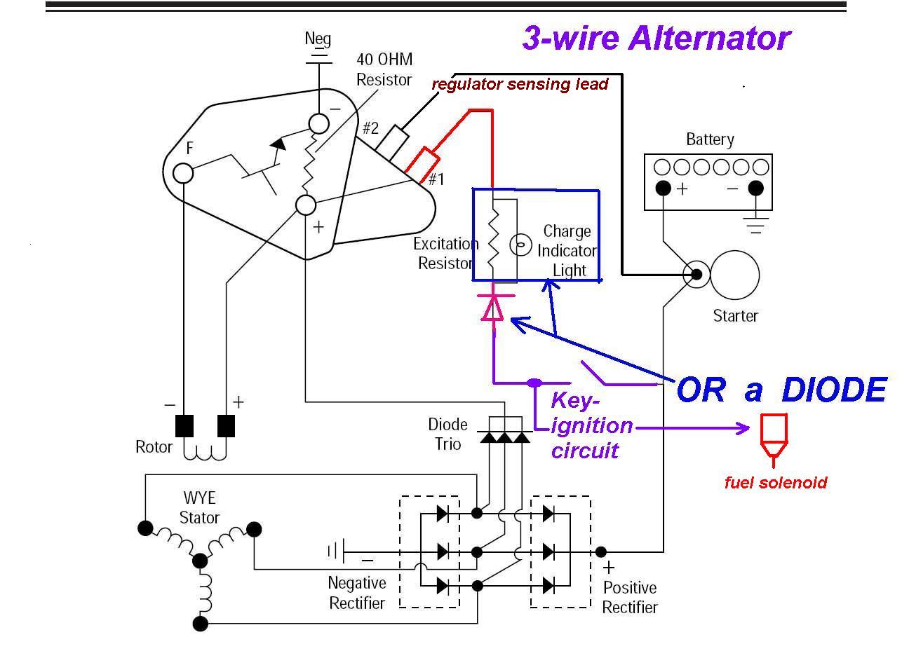
Alternator ic wiring diagrams can be extremely complex and difficult to understand. The complexity of these diagrams arises primarily from the need to accurately represent the electrical connections of an alternator circuit. An alternator is a type of generator, which typically works in conjunction with a battery and other electrical components, such as a voltage regulator, to create a charging system that is capable of providing power to a designated load.
The alternator circuit consists of a number of different components, all of which must be accurately represented in order to ensure the proper operation of the circuit. In order to do this, the wiring diagram must be able to accurately depict the various connections between the different components. This requires a detailed understanding of the electrical connections involved in the system, as well as how the different components interact.
Alternator ic wiring diagrams can be used to identify the exact connections between the components in a given system. This can ensure that the circuit is properly connected and functioning correctly. By understanding the connections between the components, it is possible to troubleshoot any issues that may arise in the system and ensure that the charging system is able to provide the necessary power to the designated load.
In addition to providing a detailed understanding of the connections between the components in a given system, alternator ic wiring diagrams can also be used to identify any potential problems that could arise in the system. This can help to prevent any malfunctions or damage that could occur due to inadequate wiring. Understanding the connections between the various components of the system can also help to ensure that all components are operating correctly and that the entire system is functioning as intended.
Alternator ic wiring diagrams can be an invaluable tool for anyone involved in designing, building, or maintaining an alternator circuit. By understanding the complexities of the electrical connections involved, it is possible to ensure that the system is functioning correctly and that the components are correctly connected. This can help to ensure that the system is able to provide the necessary power to the designated load.

Alternator Voltage Regulation 101 With Wiring Diagrams In The Garage Carparts Com
Any Alternator Experts Here
7th Unit Dynamo Amp Alternator

Ic Voltage Regulators With Circuit Diagram Design Theory

Designing A Microcontroller Driven Alternator Voltage Regulator Embedded Com

File Corolla Alternator Wiring Diagram Externally Regulated Jpg Rollaclub

Automotive Alternator Ac Circuits Electronics Textbook
Chevy 235 Alternator Wiring The H A M B
Need Help 3b Alternator Regulator Page 2 Ih8mud Forum

3 Wire Alternator Regulator Diagram Seaboard Marine

23215 4m800 Genuine Nissan 232154m800 Ic Regulator

Alternator Trouble Shooting

3 Phase Motorcycle Voltage Regulator Circuits Homemade Circuit Projects
Yanmar 3ym30 Where Do I Find The Tacho Sensor Point Page 3 Cruisers Sailing Forums
Rrj Tv Random Tutorial Alternator Wiring Diagram Facebook
Rec 010 Original Alternator Ic Regulator 55amp 24v For Use On Truck Hino Jo8c Ho7c Lorry Sho Malaysia

Alternator Wire Diagram Clublexus Lexus Forum Discussion
Wire Harness Installation Instructions

